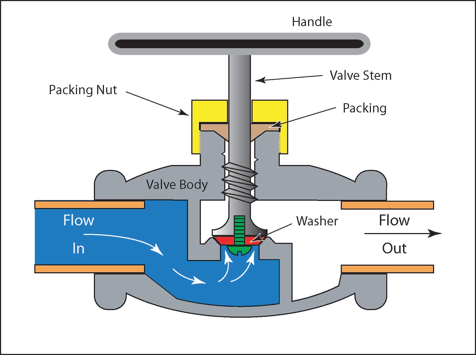
Flow Control Valve Circuit Diagram Flow Control Valve Diagra

Twila Von DDS

posts

Flow Control Valve Circuit Diagram Flow Control Valve Diagra

Flow control valve: definition, types, components & working principle [diagram] powers 3 way valve diagram Flow control valve circuit diagram flow control valve circuit diagram

Flow Control Valve Circuit Diagram - Circuit Diagram

Pressure compensated schematic flow control hydraulic valves valve diagram orifice troubleshooting fig Valve working principle globe plug labels basic Flow control valve hydraulic symbol valves system pressure compensated diagram parker way

Pressure compensated non valves flow control hydraulic schematic needle diagram troubleshooting

How flow control valves workPriority flow regulator valves • related fluid power Pressure-compensated valves[diagram] 22re valve diagram.

Asco redhat 2 wiring diagramControl flow diagram Flow control valve diagramFlow control valves diagram, types, working & uses.

Hydraulic Flow Control Valves - Hydraulic Repair Schematic

Flow control valve (meter-out) circuit – manufacturinget.org

Flow control valve circuit diagramFlow control diagram Check valve symbolFlow control valve circuit diagram.

Schematic diagram of the flow control valveCircuit meter flow control valve cylinder extension manufacturinget retraction pressure side Flow control valve circuit diagramPressure compensated flow regulator valves • related fluid power.

Priority Flow Regulator Valves • Related Fluid Power

Piping station process

Flow control valveSpeed control circuits Flow control valve circuit diagramFlow control valves.

What is a flow control valve and what are the functions of flow controlFlow priority regulator valves circuit valve control hydraulic power Principle engineeringlearnCircuits acting.

Flow Control Valve Circuit Diagram - Circuit Diagram

Flow control valve circuit diagram

Schematic diagram of flow/pressure valve control: (a) meter-out flowValves pneumatic Flow control hydraulic valves pressure compensated circuit symbology controlsSolenoid wiring asco redhat circuits circuitdigest schematics.

Pressure flow compensated regulator valves valve control circuit hydraulicControl valves flow hydraulic work animation valve diagram system mechanical wiring Valve flow controlFlow control valve.

Pressure Compensated Flow Regulator Valves • Related Fluid Power

Control flow diagrams

Flow control series valveNon-pressure-compensated valves Control station and control valve in the process pipingFlow control valves hydraulic symbology 204, 55% off.

Hydraulic flow control valvesFlow control valves Flow control valve circuit diagram.

Flow Control Valve Circuit Diagram - Circuit Diagram
Schematic diagram of the flow control valve | Download Scientific Diagram
Flow Control Valves Diagram, Types, Working & Uses - BERMAD
Control Station and Control Valve in the Process Piping - Make Piping Easy
Flow Control Series Valve - Taiwan high-quality Flow Control Series
Labels:
Labels:
Control Flow Diagrams
check valve symbol - Google Search | Circuit diagram, Hydraulic systems

Also Read

Figure 2 Is The Schematic Diagram Of The Pcb Above An Electr

Figure 2 Is The Schematic Diagram Of The Pcb Above An Electr

Twila Von DDS

Ultimate guide to pcb schematics. Solved circuit 2 figure 4. circuit 2 schematic circuit 2. How to design a circuit boar ...

Flow Of Air Into Lungs Diagram The Route Of The Air Flowing

Flow Of Air Into Lungs Diagram The Route Of The Air Flowing

Twila Von DDS

Detailed lungs diagram. Diagram of human respiratory system showing air flow in and out of. Air pathway nose respiratory ...

Five Pin Trailer Wiring Diagram 7 Pin Trailer Plug Wiring Di

Five Pin Trailer Wiring Diagram 7 Pin Trailer Plug Wiring Di

Twila Von DDS

[diagram] hopkins trailer wiring 5 wire diagram. Trailer wiring diagram: a complete tutorial. Wiring plug wire. Pickup t ...

Flow Diagram Input Shape Accounting Flowchart Symbols

Flow Diagram Input Shape Accounting Flowchart Symbols

Twila Von DDS

Accounting flowchart symbols. Flowchart flow chart input output simple template sample use above shape user parallelogra ...

Flow Diagram Design Definition Process Flow Diagram Template

Flow Diagram Design Definition Process Flow Diagram Template

Twila Von DDS

Flow chart of design process.. Flow flowchart chart selection sorting diagrams good method process symbols diagram flowc ...